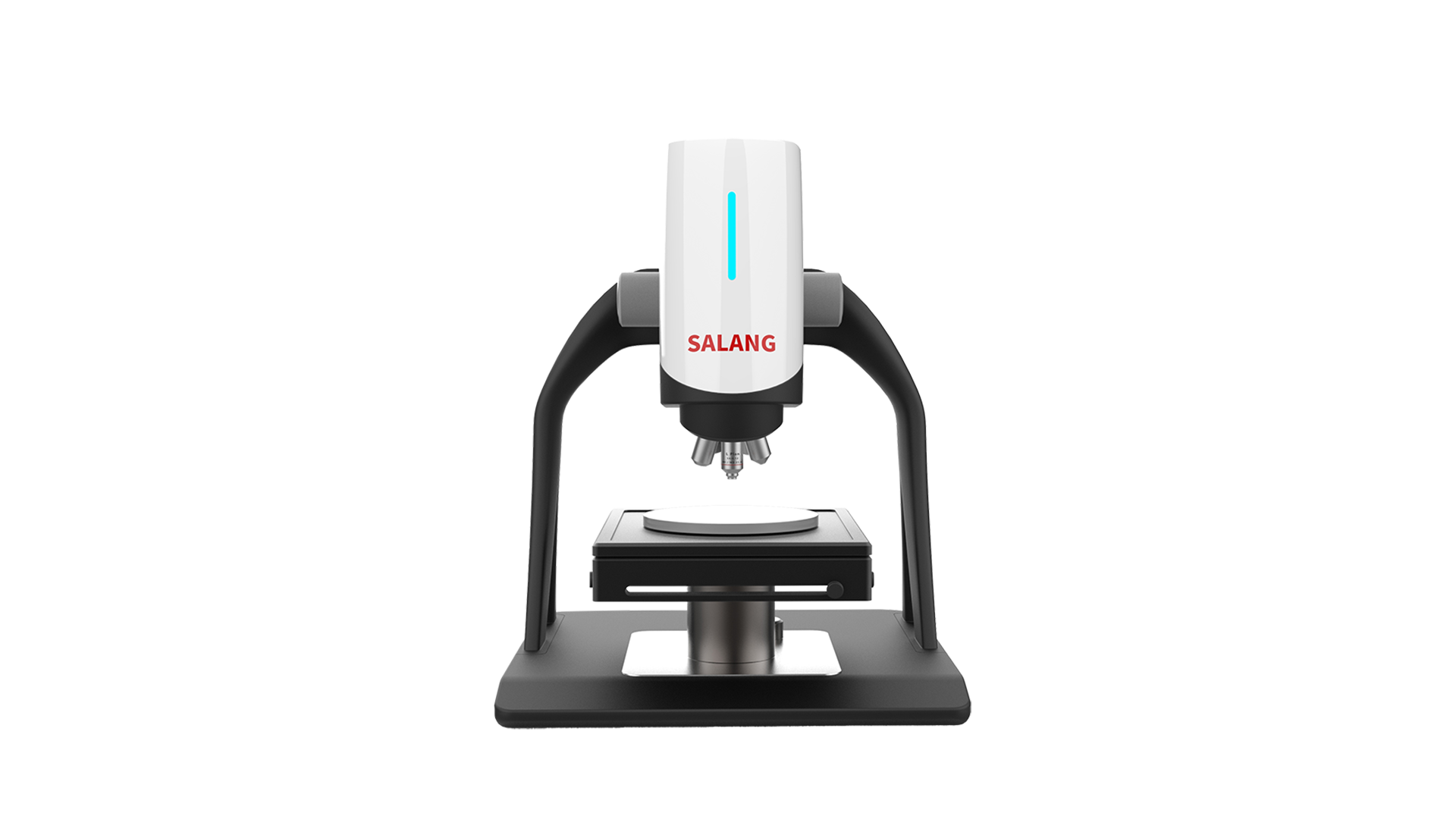
Confocal, white-light interferometry and focus variation cover 3D measurement tasks from ultra-smooth mirror surfaces to rough surfaces, steep slopes and complex microstructures. Choose the measurement method that fits the sample surface, structural height and analysis goal, then complete roughness, step-height, 3D profile and surface-feature analysis on the same platform.
For different surfaces, use more appropriate measurement methods.
The SW-1000 Series is a 3D surface measurement system that integrates three optical methods: confocal, white-light interferometry and focus variation. Each method addresses different reflection characteristics, roughness, slopes and height changes, allowing ultra-smooth mirrors, conventional precision surfaces, rough metals, thin-film steps, grooves and complex microstructures to be measured on the same platform.
Users can select measurement paths based on sample condition and analysis goals, then complete area setup, data acquisition, tilt and shape correction, roughness calculation, step and profile analysis, and report output in unified software. Data from different methods enters the same analysis process, reducing time and result differences caused by switching devices, repositioning samples and repeating processing.
02 / Integration of three measurement methods
Mirror surfaces, rough surfaces and steep slopes are handled on the same system.
SW-1000 integrates confocal, white-light interferometry and focus variation into the same measurement platform. White-light interferometry focuses on ultra-smooth continuous surfaces and small height changes; confocal measurement suits conventional precision surfaces and microstructures; focus variation suits rough surfaces, steep slopes and larger height changes. Users can choose the appropriate method for the sample without configuring separate devices for different surfaces.
03 / White-Light Interferometry and ICA height extraction
From the interference peak, the true surface height is extracted.
White light forms an interference signal after reflection from the reference optical path and the measurement optical path. A high-contrast zero-order interference peak appears only when the optical path difference is close to zero. The system records each pixel's interference response through Z-axis scanning, then uses ICA correlation processing to determine the height position of each pixel and form 3D surface data.
Z-axis scan
Pixel interference signal
Zero order interference peak
Height position
3D surface
04 / Roughness, steps and 3D Profile
From microscopic fluctuations to structural heights, analyzable data is formed.
The system analyzes surface roughness, step height, grooves, micro-pillars and 3D profiles. After data acquisition, the software can perform tilt and macro-shape correction, then calculate roughness parameters, regional height differences, section dimensions and structural morphology from the surface height distribution.
Surface roughnessStep Height3D Profile
05 / Mapping and large-area 3D measurement
From a single field of view, expand to the complete surface.
For samples beyond a single field of view, the system can be used with a motorized XY platform to perform multi-point mapping acquisition and splice multiple local 3D data into a more complete surface result. Users can switch between overall flatness, regional topography and local details, suitable for wafer, glass, film, precision parts and other large flat samples.
Single-view 3D dataXY Multi-Point AcquisitionMapping StitchingComplete 3D surfaceLocal Area Review
06 / Software workflow and result output
From sample placement, to verifiable measurement results.
The software connects measurement-area setup, optical-path and mode selection, data acquisition, noise processing, coordinate conversion, tilt correction, 2D/3D/profile analysis and report output in one process. Users can build measurement tasks around key areas and save images, 3D data, roughness, step and dimensional results.
Use 3D height distribution to calculate surface roughness parameters.
The system obtains height information for each pixel in the measurement area through vertical scanning, then removes macro tilt and shape trends before analysis. After preprocessing, roughness parameters such as Sa, Sq, Sz, Ssk and Sku can be calculated from micro-height deviations and reviewed together with the 3D surface, 2D height map, profile and statistical results.
02 / Step Height
Lock onto the high and low surfaces to measure the true height difference.
In white-light interferometry, the system captures the zero-order interference peaks of the lower and upper step planes and records the corresponding Z-axis positions. Through regional mean, profile or datum analysis, it can obtain the height difference of films, coatings, wafer structures and other fine steps.
03 / 3D Profile
Reconstruct grooves, micro-pillars and complex undulations as 3D structures.
The system can obtain macro and micro 3D morphology of the sample surface, then analyze grooves, micro-pillars, pits, bulges, wear and machining textures. Through coordinate conversion, tilt correction and area extraction, users can further obtain profile, size, volume and morphology results.
04 / Mapping and software
From local measurements, connect to complete samples and analysis reports.
For samples that need larger-area coverage, the system can perform multi-point acquisition and mapping stitching through the motorized XY stage. Users can select key areas in the overview, continue with roughness, step, section and 3D analysis, and use the results for R&D records, quality review and report output.
Configuration and expansion
Configured around sample, working distance and measuring range combinations
SW-1000 is built around the Three-in-One Composite Measurement Head and can be configured with objectives, stages and expansion platforms according to sample size, surface condition, working distance, measurement area and automation requirements. The best combination is not defined by simple high or low tiers, but by the actual sample and measurement task.
SW-1000: Configurable around measuring heads, objectives, stages and project expansion combinations.
Three-in-One Composite Measurement Head
Three measurement methods share the same measurement platform.
The measuring head integrates three optical methods: confocal, white-light interferometry and focus variation. Users can choose a suitable path for mirror surfaces, conventional precision surfaces, rough surfaces, steep slopes and height changes, then complete analysis in unified coordinates and software.
Select the objective lens according to the field of view, working distance and structural scale.
The system can be configured with conventional objectives, long-working-distance objectives, achromatic objectives and interferometry-related objectives to adapt to different fields of view, space constraints, sample heights and surface measurement tasks. Objective scope and compatibility are subject to the official configuration plan.
Standard Objective · Long Working Distance · Interferometry ConfigurationStage and Mapping
From single point measurement to large area and batch tasks.
The motorized XY stage, wafer stage, tilt platform or large sample platform can be configured according to the sample size and measurement range, and the measurement area can be expanded through multi-point mapping. The specific stroke, load-bearing and splicing capacity are subject to the selected platform.
Extensions are reserved for special angles, sample space and automated processes.
For multi-angle measurement, special tooling, heightened samples or automated inspection processes, project expansions such as five-axis measurement platforms, customized stages, triggering and data interfaces can be evaluated. Such capabilities are project configurations and are not standard by default for all equipment.
The following content describes the main measurement methods, analysis capabilities and optional configurations of SW-1000. Specific accuracy, range, objective lens, platform stroke, measurement speed and environmental parameters are subject to the official specifications and project configuration.
Wafer surface roughness, film steps, trenches, micro-pillars and 3D morphology measurement for MEMS structures and packaging.
Precision Machining
Tools, molds, sealing surfaces, grinding textures, machining roughness, wear and surface profile analysis of complex parts.
Optics and Coatings
Height and roughness measurement for mirrors, optical components, ultra-smooth continuous surfaces, films and coating steps.
Electronics, New Energy and Materials
Solder joints, ceramic substrates, electrode sheets, coatings, corrosion, wear, rough metal and material surface 3D Analysis.
Start with the sample surface, then choose the right measurement method.
Submit the sample material, surface condition, structural height, measurement area and analysis target. Engineers will help determine the confocal, white-light interferometry, focus variation and platform configuration strategy.